Abstract
This thesis deals with the study, design, development and operation of a telecommunications subsystem combining sensors and UAVs. The implementation is based on an Arduino microcontroller platform and it is equipped with sensors and transceivers. The purpose of the subsystem is the wireless collection and recording of measurements from ground-based sensors via a UAV. Field tests were performed in order to evaluate the subsystem range and operation functionality.
Equipment – Modules
- Microcontrollers: Arduino Uno (x2) and Arduino Nano (x2)
- Prototyping shields with mini breadboard for Arduino Uno (x2)
- Transceivers: 2.4 GHz wireless RF modules nRF24L01+ (x2) and nRF24L01+ modules with PA, LNA and SMA antenna (x2)
- Socket adapters for 8 pin nRF24L01+ wireless transceivers (x4)
- Temperature and humidity sensor module DHT11 (x1)
- Soil moisture sensor and hygrometer module (x1)
- Real Time Clock module DS3231 (x1)
- LCD 16x2 character I2C module (x1)
- 5 V Relay module board (x1)
- SD card reader module (x1)
- SD card 4 GB (x1)
- Power banks 2200 mAh (x2)
- 9 V batteries (x2)
- 9 V T-type battery connectors to barrel jack (x2)
- USB cables (A to mini B) (x2)
- Jumper cable wires (M/F dupont, F/F dupont, M/M solderless flexible for breadboard)
Configuration
The subsystem consists of 4 units. The user device (see Fig. 1), which consists of 1 Arduino Nano, 1 nRF24L01+ transceiver with PA and LNA, an SMA antenna and 1 LCD display.
The device which is mounted on the UAV (see Fig.2) consists of 1 Arduino Nano, 1 nRF24L01+ transceiver with PA, LNA and SMA antenna, 1 SD card storage unit and 1 Real Time Clock (RTC).
The first ground device consists of 1 Arduino Uno, 1 prototyping shield with a mini breadboard, 1 nRF24L01+ transceiver and sensors for both air temperature and humidity.
The second ground device consists of 1 Arduino Uno, 1 prototyping shield with a mini breadboard, 1 nRF24L01+ transceiver, a soil moisture sensor, a 5 V relay module and 1 AC motor.
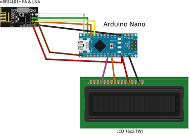 Fig. 1: The components of the user device.
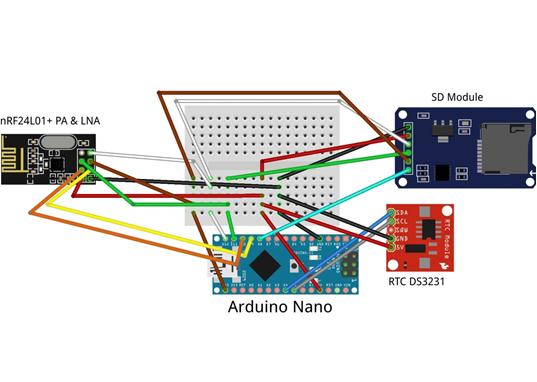 Fig. 2: The components of the device mounted on the UAV.
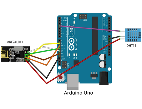 Fig. 3: The components of first ground sensor station.
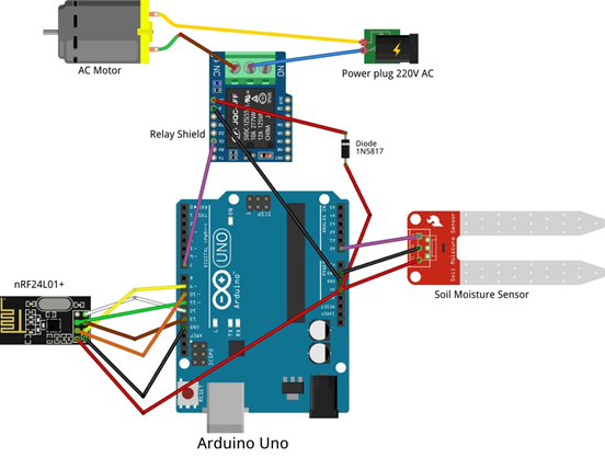 Fig. 4: The components of second ground sensor station.
UAV assisted monitoring subsystem
The aim of the subsystem is the wireless collection and storage of data from ground sensors. The operation of the individual units of the subsystem is as follows:
The first sensor checks the air temperature and humidity and the second the soil moisture. Moreover, the device of the second sensor is able to control an electric watering motor depending on the sensor measurements.
The UAV device collects data from the ground sensors, attaches a timestamp on each measurement, stores them locally at the SD card and retransmits the timestamped measurements to the user device. The UAV device sends a multicast message to the ground sensor devices in order to establish a connection. The moment each sensor device receives that message, it sends back to the UAV device the measurement of its sensor. The ground sensors stay in standby mode until they receive the multicast message from the UAV device.
As an additional feature, the user device (equipped with an LCD display) also receives data from the UAV and displays it in real time.
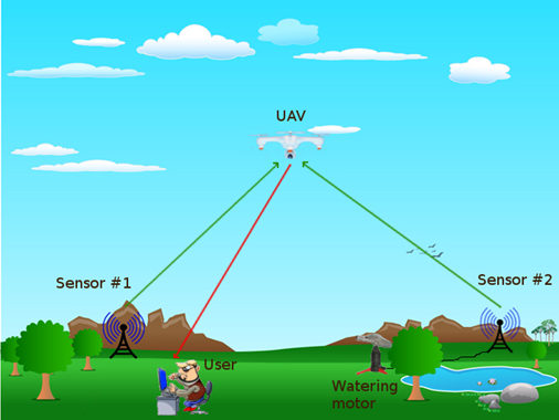 Fig. 5: UAV assisted sensor system.
Field tests
The first field test that took place in a rural area, examined only the sensoring subsystem (without the UAV). The subsystem which was used consisted of a transmitter (Fig. 3) and a receiver (Fig. 1). The transmitting end is equipped with temperature and humidity sensors so it collects measurements, associates a timestamp with each of them, stores the data locally and then transmits them to the receiver. If the receiver is within the range of the transmitter, it receives and displays the data.
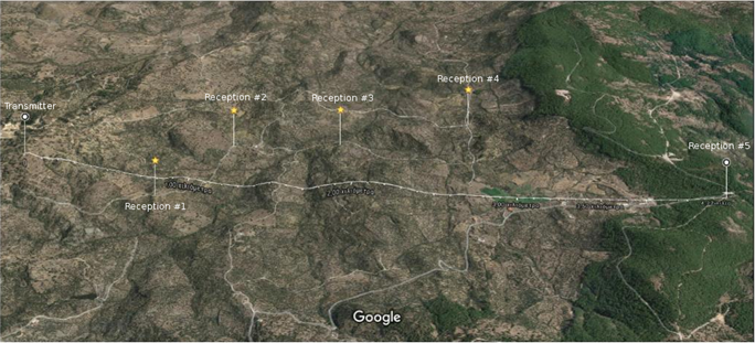 Fig. 6: First field test (location: Mytilene, Lesvos Island)
Fig. 6 depicts a map with the locations of interest regarding the first field test. The transmitter was placed on a hill and then from various locations up until the distance of 4.22 km, we had a successful reception of the transmitted data. However, the reception was successful only when there was a clear line of sight between the transmitter and the receiver.
The second test was about the UAV assisted monitoring subsystem. The picture below shows the location of both the ground sensoring units, i.e. sensor #1 and sensor #2, the location of user equipment and an approximation of the UAV flight.
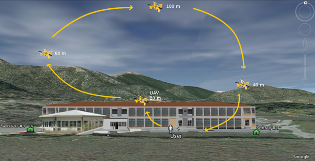 Fig. 7: Second field test (location: Department of Informatics and Telecommunications, Tripolis, Arcadia).
The following figure represents the successful receptions of the UAV device from the ground sensors. We see that sensor #2 (blue squares) remains connected to the UAV during its entire flight, while sensor #1 is activated after the UAV ascends to 40m and loses again connectivity during the UAV descent. As it was shown in Fig. 7, sensor #1 was placed behind a building of ~5m height, thus there was no visual contact with the UAV when its altitude was below 40-50 m.
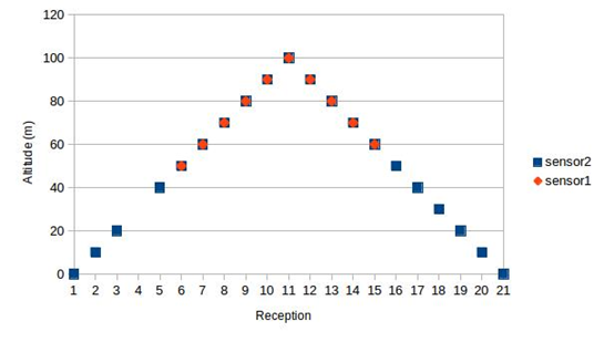 Fig. 8: Connectivity assessment between the UAV and the ground sensors during the second field trial.